Experiment Setup
- Magnitude of rotating magnetic field (RMF): ~6 mT
- Magnetic field is expressed by: [0 RMF*sin(ωt) RMF*cos(ωt)]’
where ω=2*π*f for pusher-mode and ω=-2*π*f for puller-mode. f is rotation rate of magnetic field, t is time. - Range of rotation rate of magnetic field: 1 – 25 Hz
- Current passing through the coils are controlled by LabVIEW software by means of Maxon ADS_E 50/5 motor drivers and NI DAQ hardware.
- Liquid in the channel is glycerol (Density~1264 kg/m3, Viscosity~1.412 Pa.s, refractive index~1.5)
- Experiments are recorded at 120 FPS with CASIO EX-ZR1000 digital camera.
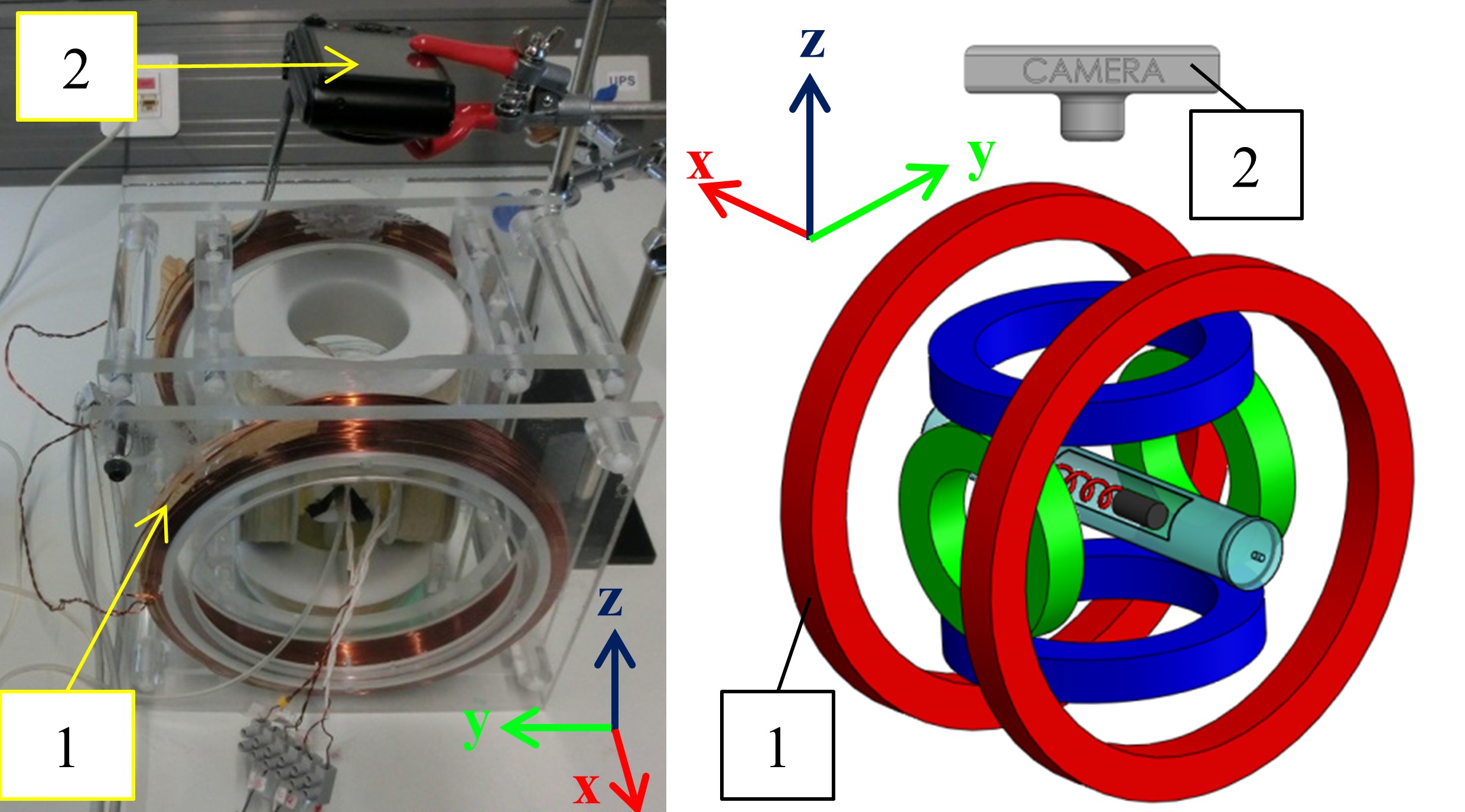
You can find a photo and schematic of the setup below. Rotating magnetic field is achieved with the help of two pairs of orthogonal Helmholtz coils.
Swimmer Properties
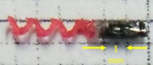
Swimmer L4.
Common Properties
- Tail minor diameter: 0.2 mm
- Tail major diameter: 0.8 mm
- Head length: 1.5 mm
- Head diameter: 0.88 mm
- Magnet length: 1.5 mm
- Magnet diameter: 0.8 mm
Swimmer L1.5
- Tail length: 1.5 mm
Swimmer L4
- Tail length: 4 mm
Channel Properties
Cylindrical channels made of glass (with a refractive index of ~1.5) are used in the experiments.
- Channel D1.6: Inner diameter of 1.6 mm and wall thickness of 0.7 mm
- Channel D3: Inner diameter of 3 mm and wall thickness of 0.72 mm
Flow in the Channel
- Q0: No flow in the channel (flow velocity of 0 mm/s)
- Q10: 10 mL/min flowrate for a reference channel with a diameter of 1 mm (average flow velocity of 0.207 mm/s)
- Q20: 20 mL/min flowrate for a reference channel with a diameter of 1 mm (average flow velocity of 0.414 mm/s)
- Q30: 30 mL/min flowrate for a reference channel with a diameter of 1 mm (average flow velocity of 0.621 mm/s)
Supplementary Material
In the sections below, you can find supplementary material related to the publication:
Caldag, H. O., Acemoglu, A. & Yesilyurt, S. (2017). Experimental characterization of helical swimming trajectories in circular channels. Microfluidics and Nanofluidics 21:136. Springer Berlin Heidelberg https://doi.org/10.1007/s10404-017-1973-9
Videos
Experiment recordings are attached below for magnetic field rotation rates of 11-15 Hz both in pusher and puller modes. – sign in file name implies puller mode. The folders the videos are placed in indicate the experiment configuration. Letter D stands for channel diameter, L stands for tail length and Q stands for channel flowrate.
Experiment Videos.zip
You can download the videos individually from the links at the bottom of the page.
Processed Data
Processed data of experiment videos reported in the article can be found below. Refer to Readme.txt for information on usage of files.
Processed Data.zip
Image Processing Code
The code package in the link below is composed of 3 MATLAB scripts. image_processing.m script is used for processing experiment videos to extract position and orientation information to .dat files. data_processing.m script evaluates relevant data from generated .dat files and shows the results in various plots. This script also calls image_corr.m function to correct the position information and eliminate the effects of refraction of light.
Note: You need Image Processing Toolbox to run image_processing.m.
Image Processing.zip
Separate Links for Each Experiment Video
You can find separate download links for each experiment video in Experiment Videos.zip file below.
A) Swimmer L1.5 in channel D1.6
1) No Poiseuille flow (Q0)
a) Pusher-mode (ω>0)
i) 11 Hz
ii) 13 Hz
iii) 15 Hz
b) Puller-mode (ω<0)
i) -11 Hz
ii) -13 Hz
iii) -15 Hz
2) Poiseuille flow with 0.207 mm/s average velocity (Q10)
a) Pusher-mode (ω>0)
i) 11 Hz
ii) 13 Hz
iii) 15 Hz
b) Puller-mode (ω<0)
i) -11 Hz
ii) -13 Hz
iii) -15 Hz
3) Poiseuille flow with 0.414 mm/s average velocity (Q20)
a) Pusher-mode (ω>0)
i) 11 Hz
ii) 13 Hz
iii) 15 Hz
b) Puller-mode (ω<0)
i) -11 Hz
ii) -13 Hz
iii) -15 Hz
4) Poiseuille flow with 0.621 mm/s average velocity (Q30)
a) Pusher-mode (ω>0)
i) 11 Hz
ii) 13 Hz
iii) 15 Hz
b) Puller-mode (ω<0)
i) -11 Hz
ii) -13 Hz
iii) -15 Hz
B) Swimmer L4 in channel D1.6
1) No Poiseuille flow (Q0)
a) Pusher-mode (ω>0)
i) 11 Hz
ii) 13 Hz
iii) 15 Hz
b) Puller-mode (ω<0)
i) -11 Hz
ii) -13 Hz
iii) -15 Hz
2) Poiseuille flow with 0.207 mm/s average velocity (Q10)
a) Pusher-mode (ω>0)
i) 11 Hz
ii) 13 Hz
iii) 15 Hz
b) Puller-mode (ω<0)
i) -11 Hz
ii) -13 Hz
iii) -15 Hz
3) Poiseuille flow with 0.414 mm/s average velocity (Q20)
a) Pusher-mode (ω>0)
i) 11 Hz
ii) 13 Hz
iii) 15 Hz
b) Puller-mode (ω<0)
i) -11 Hz
ii) -13 Hz
iii) -15 Hz
4) Poiseuille flow with 0.621 mm/s average velocity (Q30)
a) Pusher-mode (ω>0)
i) 11 Hz
ii) 13 Hz
iii) 15 Hz
b) Puller-mode (ω<0)
i) -11 Hz
ii) -13 Hz
iii) -15 Hz
C) Swimmer L4 in channel D3
1) No Poiseuille flow (Q0)
a) Pusher-mode (ω>0)
i) 11 Hz
ii) 13 Hz
iii) 15 Hz
b) Puller-mode (ω<0)
i) -11 Hz
ii) -13 Hz
iii) -15 Hz
2) Poiseuille flow with 0.207 mm/s average velocity (Q10)
a) Pusher-mode (ω>0)
i) 11 Hz
ii) 13 Hz
iii) 15 Hz
b) Puller-mode (ω<0)
i) -11 Hz
ii) -13 Hz
iii) -15 Hz
3) Poiseuille flow with 0.414 mm/s average velocity (Q20)
a) Pusher-mode (ω>0)
i) 11 Hz
ii) 13 Hz
iii) 15 Hz
b) Puller-mode (ω<0)
i) -11 Hz
ii) -13 Hz
iii) -15 Hz
4) Poiseuille flow with 0.621 mm/s average velocity (Q30)
a) Pusher-mode (ω>0)
i) 11 Hz
ii) 13 Hz
iii) 15 Hz
b) Puller-mode (ω<0)
i) -11 Hz
ii) -13 Hz
iii) -15 Hz